1 Benchwork for inside model railways
All railway modellers use some kind of benchwork, if we allow the widest definition of the thing. In many cases it is unclear if the modeller talks about the supporting structure under the lay-out only, excluding the frame and base sheet or all included.
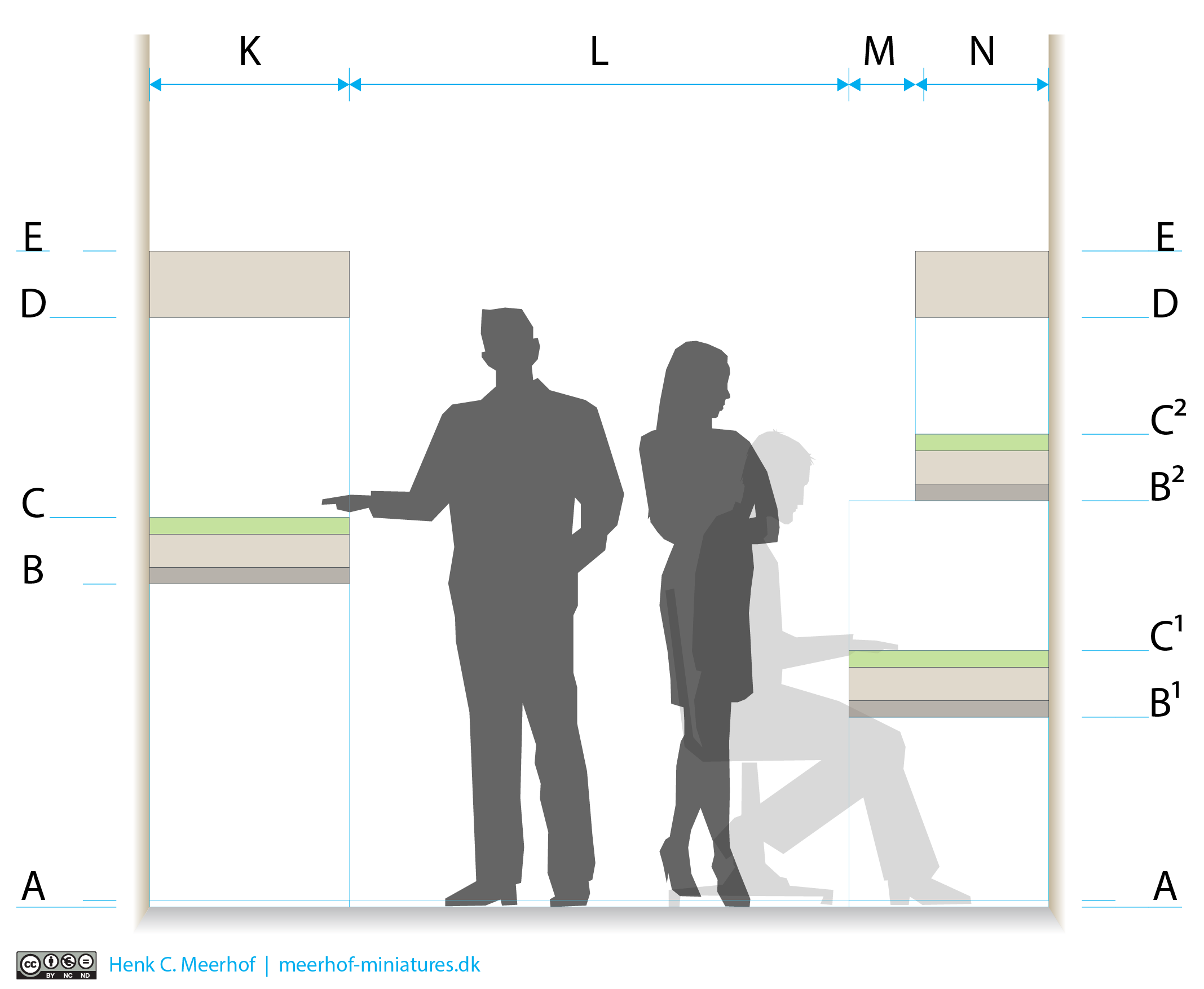
To illustrate what we are talking about a picture of a possible situation of a model railway with some adult persons as reference.
To keep things clear here I will only talk about the supporting structure, that in some cases is fixed to the frame of the layout or even form one solid unit with it.
In the drawing it is in the space between the floor up to and including the darker brown band just over the B(1) level.
The lighter brown layer is the lay-out frame and the green layer the top sheet on which track and scenery.
Image 1
The most easy form of benchwork is just a table or work surface. The lay-out can easy be put on one and removed after use. Of course this easy solution will limit things like the size of the lay-out. On the positive side, you can start your rail empire with only a starter set…
For all dedicated forms of bench work the same criteria are in play.
-
it has to fit the room/space you dedicated to the model railway.
-
it has to support your entire lay-out, depending of materials used and the need to lean on the lay-out to reach for the middle or back of the lay-out, the supporting structure need to be sturdy enough to allow for this and a bit more.
-
it has to allow to work on the bottom of the lay-out, as here you will have a great part of the technical installations like wiring, turnout motors and other means of animation, maybe even sound.
There are many choices to be made all depending you skills and preferences.
But also choices about how you can or want to run your trains.
If you live in a small space, a lay-out that you can store safely while not in use can be one of those decisions. More space, more possibilities to make a permanent lay-out. The bench work will be integrated part of those decisions.
We start with the smallest of the small.
Shoe box to suitcase lay-outs
Generally those are satisfied with some kind of table to put them on. Hook your controller up and you are away (building of such a lay-out is a different thing)
Shelf lay-outs
The key is in the name, those can be very long, as long as your wall(s) allow, but shallow often no more than 300-400 mm [ measurement N in the picture ] or 12-16 inch wide.
C in the picture above
500- 600 mm or 1.6-2.0 ft if you want to be able to see trains running while sitting on your sofa.
700- 800 mm or 2.3-2.6 ft on worktable heigth
950-1050 mm or 3.1-3.4 ft for standing
1200-1300 mm or 4.0-4.2 ft, upper limit for standing as upper level because the average shorter adult wil get a hard time getting a good look on this high level.
With multy level shelves you can use the idea in the illustration.
K 600 mm or 2.0 ft deep for the lower shelf.
N 400 mm or 1.3 ft deep for the upper shelf.
A in the picture above
This area is 20 mm or 0.8 inch on the drawing, it is not a special measurement on its own. It just allows for adjustable feet under your supports so you can get the lay-out level and all supports bearing their weight.
Image 2
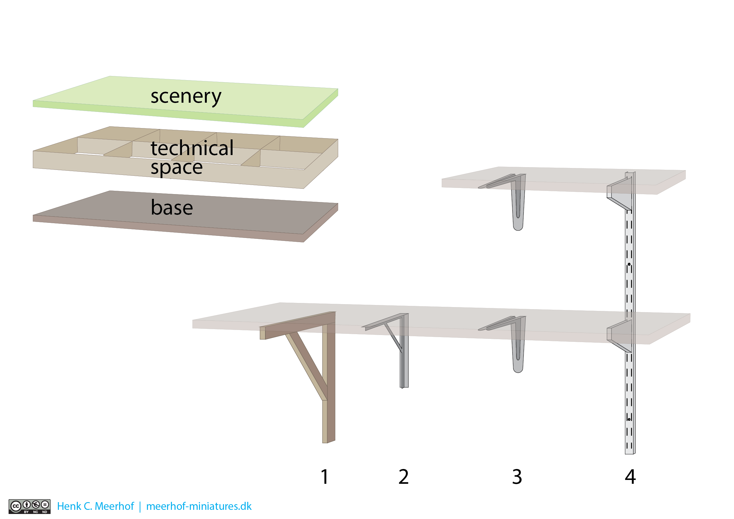
Like normal shelves they can be supported by any shelf bearing system visible or hidden.
In the picture 1 wooden supports, 2 heavy steel supports, 3 metal L-supports, 4 rail-systems
You can choose to make the entire lay-out (base, technical space and scenery layer) fixed to the wall supports but consider having the supporting system as a separate part under or in the lay-out frame(s). A free supporting system allows you to take the lay-out from it’s support for working on it. You can even design the lay-out in segments, so work on them is even more easy. Segments are also a clever way to be prepared for moving to another room or house even. Segments are also great for technical reasons, as you will wire and add other technical features to the segment. In case of technical maintenance or errors you can quick find out in which segment the issue originates and try to resolve it.
A shelf lay-out could be part of a larger lay-out to move trains from one side of a room to another.
Small permanent lay-outs
Those would be up to about 1800-2400 mm or 6-8 ft in length and 600-1200 mm or 2-4 ft in width.
Image 3
Those measurements are not just made up, they are based on standard building materials, so you waste as little as possible when using sheet materials. These measurements are only indications, as you will be adapting them to both your available space and you ideas about how the lay-out will look like.
We are talking about the size of a door or decent table, so maybe that would be the most practical thing to use as your base.
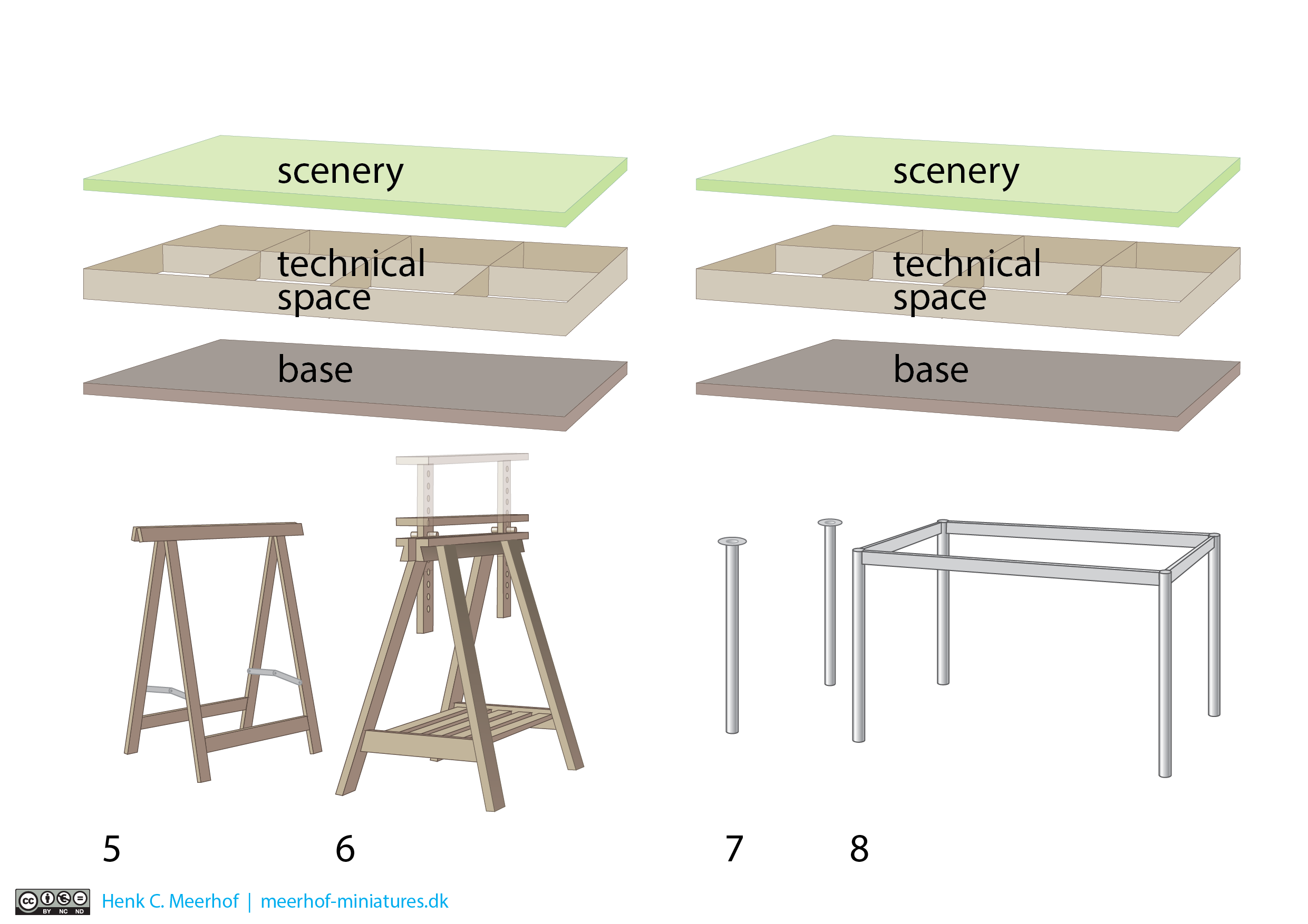
This base can be supported in many ways, also here you could revert to standard available materials like pre-fab table legs or trestle of some kind.
In the picture 5 cheap prefab or self made jacks, 6 industrial made jacks that can be adjusted (this one is inspired by a swedish flat pack furniture company, 7 Prefab or self made table legs, 8 complete prefab table support.
If you decide to use a table to build on you have all the parts in place. The only thing you have to decide is if the height is right for you and where you will be fitting the technical installation for your lay-out. The ‘no-brainer’ solution is of course track and scenery on top, wiring and technical under it… but there are alternatives. You can build the layout in sections that fit on top of the table, leaving the table unchanged for other use.
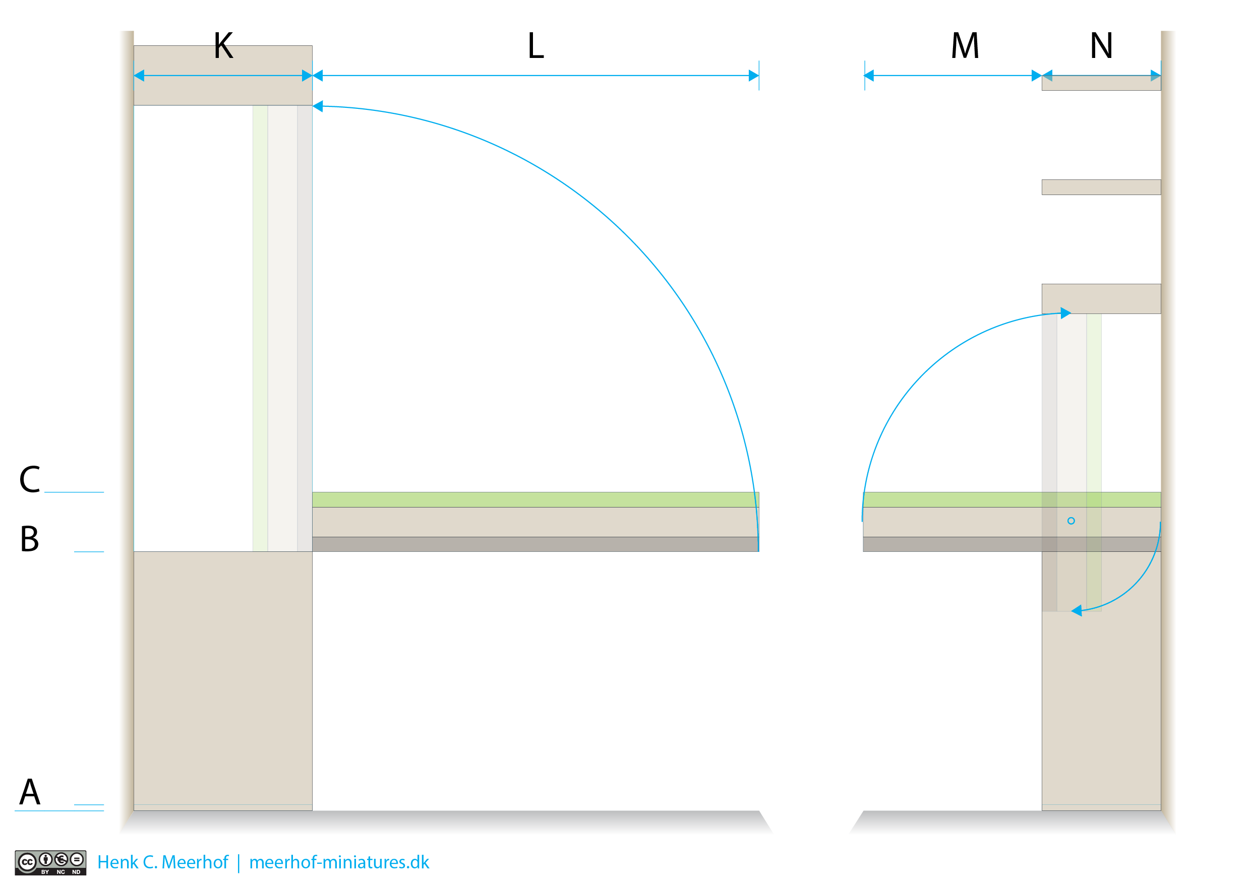
In smaller rooms you have an alternative in hinging your lay-out to the wall or as part of a smart wall-closet. Disadvantage here is you need careful planning and good skills to pull it off in a nice way. Advantage, you just lower the lay-out and you are ready to roll.
Image 4
In the illustration with a lay-out on hinges (left) or pivot point (right)
B 870 mm or 2.8 ft above the floor, the space can be used for storage.
C 890 mm or 2.9 ft above the floor, top of scenery layer when the lay-out is down.
K 600 mm or 2.0 ft deep for the entire closet.
L 1500 mm or 4.9 ft deep when the lay-out is down.
M 600 mm or 2.0 ft deep when the lay-out is down.
N 400 mm or 1.3 ft deep for the entire closet.
There are even hoist systems where the entire lay-out is raised to just under the ceiling. If you choose this solution, make very sure your system is capable of handling the weight and have some security fixations to hold all 'up there'.
I would not go with this as it is rather complicated to make and I have experienced something that should be staying up, falling down on my car. Lucky for me, I only had to replace the front window, but it could have been much worse.
Larger lay-outs
Those are in most cases permanent, often utilize attic or basement space, some even have a dedicated building for the purpose. Bench work of this level need not to be addressed as something special. The same rules apply for them as for smaller fixed lay-outs, just on a larger scale. Often though these lay-outs call for special solutions to technical issues like wiring ducts, secure power and data busses, access to remote places and more.
Modular systems
I already mentioned lay-outs that are build in sections. You can also choose to build not a fixed lay-out, but modules. These are standardised elements, so each will fit together with the next, no matter if that next module is yours, mine or belonging to the next person.


